Highlight:
SO Carbon Steel Flange
, Class 150 SO RF Flange
, RF Carbon Steel Flange
Product Name: |
2"ASTM A105N ANSI B16.5 SO RF Class 150 Carbon Steel Flange |
Size: |
2" |
Pressure Class: |
150 |
Standard: |
ASTM A105N |
Face Type: |
SO-RF Slip-On Raised Face |
Coating: |
Anti-rust Paint, Could And Hot Dip Galvanized, Zinc Plated, Yellow Transparent, Oil Black Paint |
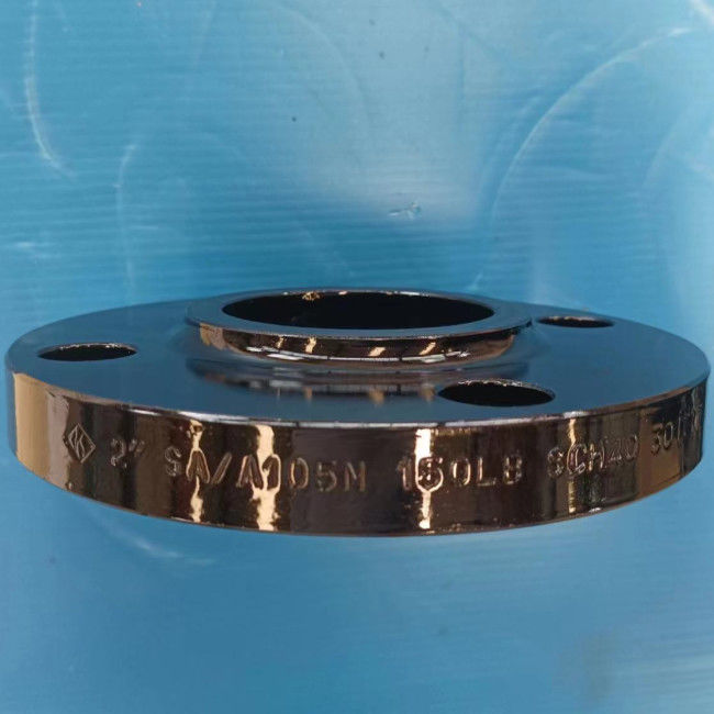
Class 150 Carbon Steel Flange 2" ASTM A105N ANSI B16.5 SO RF Industrial
2"ASTM A105N ANSI B16.5 SO RF Class 150 Carbon Steel Flange
Product Information
| Product Name |
2"ASTM A105N ANSI B16.5 SO RF Class 150 Carbon Steel Flange |
| Size Range |
2” |
| Pressure Class |
Class 150 |
| Standards |
ASTM A105N |
| Face Type |
SO RF Slip-On Raised Face |
| Specification |
ANSI B16.5 |
| Coating |
Anti-rust Paint, Could and Hot Dip Galvanized, Zinc Plated, Yellow Transparent, Oil Black Paint |
ASTM A105/A105N
ASTM A105 flanges are forged carbon steel flanges for ambient- and higher-temperature service in pressure systems. These flanges may be manufactured in accordance with a variety of standard specifications covering ASME B16.5, ASME B16.47, ASME B16.48, ASME B16.36, MSS SP 44, API 605, and API 6A, etc. Flanges made to ASTM A105 material are limited a maximum weight of 4540 kg.
ASTM A105 and A105N steel flanges are not same, they have same raw materials, same steel grades, but different heat treatment requirement. N means Normalization heat treatment, and A105 flange haves no heat treatment requirement. In summary, the ASTM A105 flange and ASTM A105N flange have a same chemical composition, but the A105N have a better mechanical property and usually used in critical situation.
ASTM A105 Chemical Composition (%)
| Steel Class |
C
max
|
Si |
Mn |
P
max
|
S
max
|
Ni
max
|
Cr
max
|
Mo
max
|
V
max
|
| A105 |
0.35 |
0.10-0.35 |
0.60-1.05 |
0.035 |
0.040 |
0.40 |
0.30 |
0.12 |
0.08 |
ASTM A105 Mechanical Properties
| Steel Class |
Tensile Strength
min
(MPa)
|
Yield Strength
min
(MPa)
|
Elongation
min
(%)
|
Reduction of Area
min
(%)
|
Hardness
(HBW)
|
| A105 |
485 |
250 |
22 |
30 |
137-187 |
ANSI B16.5 Flange Dimensions - Class 150

| Nominal Size |
Outside Dia. |
Thickness |
Length thru Hub |
Dia. of Hub |
Raised Face Dia. |
Corner Radius of Bore |
Depth of Socket |
Counter Bore |
Thread Length |
Bolt Holes |
| WN |
SO
SW
TR
|
LJ |
LJ |
SW |
TR |
Bolt Circle Dia. |
No |
Dia. |
| A |
B |
O |
t |
Y1 |
Y2 |
Y3 |
X |
R |
r1 |
D |
B4 |
Q |
C |
H |
| 15 |
1/2 |
89 |
11.2 |
47.8 |
16 |
30.0 |
35.1 |
3 |
10 |
Chamfered to major dia. of thread at 45o |
16 |
60.5 |
4 |
16 |
| 20 |
3/4 |
99 |
12.7 |
52.3 |
16 |
38.0 |
42.9 |
3 |
11 |
16 |
69.8 |
4 |
16 |
| 25 |
1 |
108 |
14.3 |
55.6 |
18 |
49.5 |
50.8 |
3 |
13 |
18 |
79.2 |
4 |
16 |
| 32 |
1-1/4 |
117 |
15.8 |
57.2 |
21 |
58.5 |
63.5 |
5 |
14 |
21 |
88.9 |
4 |
16 |
| 40 |
1-1/2 |
127 |
17.6 |
62.0 |
22 |
65.0 |
73.2 |
6 |
16 |
22 |
98.6 |
4 |
16 |
| 50 |
2 |
152 |
19.1 |
63.5 |
25 |
77.5 |
91.9 |
8 |
18 |
25 |
120.6 |
4 |
19 |
| 65 |
2-/21 |
178 |
22.4 |
69.8 |
28 |
90.5 |
104.6 |
8 |
19 |
28 |
139.7 |
4 |
19 |
| 80 |
3 |
190 |
23.9 |
69.8 |
30 |
108 |
127.0 |
10 |
21 |
30 |
152.4 |
4 |
19 |
| 90 |
3-1/2 |
216 |
23.9 |
71.4 |
32 |
122 |
139.7 |
10 |
|
32 |
177.8 |
8 |
19 |
| 100 |
4 |
229 |
23.9 |
76.2 |
33 |
135 |
157.2 |
11 |
|
33 |
190.5 |
8 |
19 |
| 125 |
5 |
254 |
23.9 |
88.9 |
37 |
164 |
185.7 |
11 |
|
37 |
215.9 |
8 |
22 |
| 150 |
6 |
279 |
25.4 |
88.9 |
40 |
192 |
215.9 |
13 |
|
40 |
241.3 |
8 |
22 |
| 200 |
8 |
343 |
28.5 |
101.6 |
44 |
246 |
269.7 |
13 |
|
44.4 |
298.4 |
8 |
22 |
| 250 |
10 |
406 |
30.3 |
101.6 |
49 |
305 |
323.8 |
13 |
|
49.3 |
362.0 |
12 |
22 |
| 300 |
12 |
483 |
31.8 |
114.3 |
56 |
365 |
381.0 |
13 |
|
55.6 |
431.8 |
12 |
26 |
| 350 |
14 |
535 |
35.1 |
127.0 |
57 |
79 |
400 |
412.8 |
13 |
|
57.2 |
476.2 |
12 |
29 |
| 400 |
16 |
595 |
36.6 |
127.0 |
64 |
87 |
457 |
469.9 |
13 |
|
63.5 |
539.8 |
16 |
29 |
| 450 |
18 |
635 |
39.7 |
139.7 |
68 |
97 |
505 |
533.4 |
13 |
|
68.3 |
577.8 |
18 |
32 |
| 500 |
20 |
700 |
43.0 |
144.5 |
73 |
103 |
559 |
584.2 |
13 |
|
73.2 |
635.0 |
20 |
32 |
| 600 |
24 |
815 |
47.8 |
152.4 |
83 |
111 |
663 |
692.2 |
13 |
|
82.6 |
749.3 |
20 |
35 |
| Nominal Size |
Dimensions of Ring Joint Flanges |
Weight (kg) |
| Groove Number |
Dia. of Raised Portion |
Pitch Dia. |
Depth |
Width |
Radius at Bottom |
WN
Sch 40
|
SO |
BL |
SW
Sch 40
|
LJ |
TR |
| A |
B |
K |
P |
E |
F |
r2 |
| 15 |
1/2 |
|
|
|
|
|
|
0.57 |
0.41 |
0.43 |
0.42 |
0.46 |
0.42 |
| 20 |
3/4 |
|
|
|
|
|
|
0.73 |
0.59 |
0.64 |
0.60 |
0.65 |
0.60 |
| 25 |
1 |
R15 |
63.5 |
47.62 |
6.35 |
8.74 |
0.8 |
1.03 |
0.79 |
0.87 |
0.81 |
0.86 |
0.82 |
| 32 |
1-1/4 |
R17 |
73.5 |
57.16 |
6.35 |
8.74 |
0.8 |
1.33 |
1.03 |
1.16 |
1.05 |
1.10 |
1.07 |
| 40 |
1-1/2 |
R19 |
83.0 |
65.07 |
6.35 |
8.74 |
0.8 |
1.76 |
1.36 |
1.58 |
1.38 |
1.43 |
1.41 |
| 50 |
2 |
R22 |
102 |
82.55 |
6.35 |
8.74 |
0.8 |
2.61 |
2.10 |
2.47 |
2.14 |
2.20 |
2.18 |
| 65 |
2-/21 |
R25 |
122 |
101.60 |
6.35 |
8.74 |
0.8 |
4.08 |
3.25 |
4.00 |
3.34 |
3.40 |
3.38 |
| 80 |
3 |
R29 |
134 |
114.30 |
6.35 |
8.74 |
0.8 |
4.93 |
3.87 |
4.95 |
3.99 |
4.00 |
4.05 |
| 90 |
3-1/2 |
R33 |
154 |
131.78 |
6.35 |
8.74 |
0.8 |
6.12 |
4.89 |
6.42 |
|
5.06 |
5.10 |
| 100 |
4 |
R36 |
172 |
149.22 |
6.35 |
8.74 |
0.8 |
6.96 |
5.38 |
7.09 |
|
5.55 |
5.63 |
| 125 |
5 |
R40 |
194 |
171.45 |
6.35 |
8.74 |
0.8 |
8.83 |
6.29 |
8.72 |
|
6.43 |
6.68 |
| 150 |
6 |
R43 |
219 |
193.68 |
6.35 |
8.74 |
0.8 |
10.9 |
7.77 |
11.4 |
|
7.89 |
8.27 |
| 200 |
8 |
R48 |
274 |
247.65 |
6.35 |
8.74 |
0.8 |
17.9 |
12.4 |
19.6 |
|
12.6 |
12.6 |
| 250 |
10 |
R52 |
331 |
304.80 |
6.35 |
8.74 |
0.8 |
25.0 |
17.6 |
29.1 |
|
17.8 |
17.6 |
| 300 |
12 |
R56 |
407 |
381.00 |
6.35 |
8.74 |
0.8 |
38.7 |
27.7 |
43.8 |
|
28.1 |
27.8 |
| 350 |
14 |
R59 |
426 |
396.88 |
6.35 |
8.74 |
0.8 |
51 |
35.3 |
59 |
|
47.6 |
35.2 |
| 400 |
16 |
R64 |
483 |
454.02 |
6.35 |
8.74 |
0.8 |
64 |
44.9 |
77 |
|
63.5 |
45.3 |
| 450 |
18 |
R68 |
547 |
517.52 |
6.35 |
8.74 |
0.8 |
75 |
49.3 |
94 |
|
72.6 |
49.7 |
| 500 |
20 |
R72 |
597 |
558.80 |
6.35 |
8.74 |
0.8 |
94 |
63 |
123 |
|
88.5 |
63.5 |
| 600 |
24 |
R76 |
712 |
673.10 |
6.35 |
8.74 |
0.8 |
133 |
89 |
188 |
|
124.7 |
90.5 |
Flange Type:Slip On Flange
Slip on flange also simplified as SO flange. SO flanges slip over pipes and are designed to bit slightly bigger on the inside than the pipe. They connect to the pipe through a fillet weld at the flange top and bottom. It is used to insert the pipe into the inner hole of flange, as the flange inner diameter is little bigger than the pipe’s outer diameter, pipe and flange could be connected by lap welding at the top and bottom of the flange.
The slip on flange is shorter in length than a weld neck flange, and is used in areas where short tie-ins are necessary or space limitations necessitate its use. Generally, the life span of a slip-on flange connection is about one-third that of the weld neck flange. Despite of additional welding involved during installation, its lower initial cost makes the SO flange preferred over WN flanges by many users. It is generally used in non-corrosive, non-critical, moderate pressure services. Slip on flanges of Class 150 and Class 300 are most commonly seen in utility engineering.
Face Type: Raised Face (RF)
The Raised Face flange is the most common type used in process plant applications, and is easily to identify. It is referred to as a raised face because the gasket surfaces are raised above the bolting circle face. This face type allows the use of a wide combination of gasket designs, including flat ring sheet types and metallic composites such as spiral wound and double jacketed types.
The purpose of a RF flange is to concentrate more pressure on a smaller gasket area and thereby increase the pressure containment capability of the joint. Diameter and height are in ASME B16.5 defined, by pressure class and diameter. Pressure rating of the flange determines the height of the raised face.

 Your message must be between 20-3,000 characters!
 english
 français
 Deutsch
 Italiano
 Русский
 Español
 português
 Nederlandse
 ελληνικά
 日本語
日本語
 한국
한국