Highlight:
ANSI B16.5 Carbon Steel Flange
, WN Raised Face Flange
, Class 600 Carbon Steel Flange
ANSI B16.5 Carbon Steel Flange WN RF Class 600 Weld Neck Raised Face
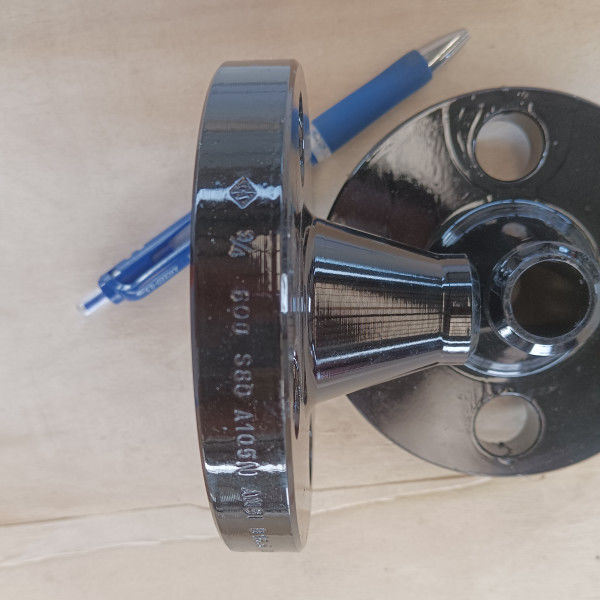
ASTM A105N ANSI B16.5 WN RF Class 600 Carbon Steel Weld Neck Raised Face Flange
Product Information
| Product Name |
ASTM A105N ANSI B16.5 WN RF Class 600 Carbon Steel Weld Neck Raised Face Flange |
| Size Range |
1/2” to 24” |
| Pressure Class |
Class 600 |
| Standards |
ASTM A105N |
| Face Type |
WNRF-Weld Neck Raised Face |
| Specification |
ANSI B16.5 |
| Coating |
Anti-rust Paint, Could and Hot Dip Galvanized, Zinc Plated, Yellow Transparent, Oil Black Paint |
ASTM A105/A105N
ASTM A105 flanges are forged carbon steel flanges for ambient- and higher-temperature service in pressure systems. These flanges may be manufactured in accordance with a variety of standard specifications covering ASME B16.5, ASME B16.47, ASME B16.48, ASME B16.36, MSS SP 44, API 605, and API 6A, etc. Flanges made to ASTM A105 material are limited a maximum weight of 4540 kg.
ASTM A105 and A105N steel flanges are not same, they have same raw materials, same steel grades, but different heat treatment requirement. N means Normalization heat treatment, and A105 flange haves no heat treatment requirement. In summary, the ASTM A105 flange and ASTM A105N flange have a same chemical composition, but the A105N have a better mechanical property and usually used in critical situation.
ASTM A105 Chemical Composition (%)
| Steel Class |
C
max
|
Si |
Mn |
P
max
|
S
max
|
Ni
max
|
Cr
max
|
Mo
max
|
V
max
|
| A105 |
0.35 |
0.10-0.35 |
0.60-1.05 |
0.035 |
0.040 |
0.40 |
0.30 |
0.12 |
0.08 |
ASTM A105 Mechanical Properties
| Steel Class |
Tensile Strength, min
(MPa)
|
Yield Strength, min
(MPa)
|
Elongation, min
(%)
|
Reduction of Area, min
(%)
|
Hardness
(HBW)
|
| A105 |
485 |
250 |
22 |
30 |
137-187 |
Flange Type:Weld Neck Flange (WN)
A weld neck flange, also called a tapered hub flange or high-hub flange, is a kind of flange that can relocate stress to the pipes, ensuring a decrease in high-stress concentration at the bottom of the flange. There are two welding neck flanges designs – the first type is used with pipes while the second, longer type cannot be used with pipes but with a process plant. The weld neck flange comprises of a round fitting that extends beyond the rim of the circumference. These flanges, typically manufactured from forging, are actually welded to pipes.
Face Type: Raised Face (RF)
The Raised Face flange is the most common type used in process plant applications, and is easily to identify. It is referred to as a raised face because the gasket surfaces are raised above the bolting circle face. This face type allows the use of a wide combination of gasket designs, including flat ring sheet types and metallic composites such as spiral wound and double jacketed types.
The purpose of a RF flange is to concentrate more pressure on a smaller gasket area and thereby increase the pressure containment capability of the joint. Diameter and height are in ASME B16.5 defined, by pressure class and diameter. Pressure rating of the flange determines the height of the raised face.
ANSI B16.5 Flange Dimensions - Class 600 (mm)

| Nominal Size |
Outside Dia. |
Thickness |
Length thru Hub |
Dia. of Hub |
Raised Face Dia. |
Corner Radius of Bore |
Depth of Socket |
Counter Bore |
Thread Length |
Bolt Holes |
| WN |
SO
SW
TR
|
LJ |
LJ |
SW |
TR |
Bolt Circle Dia. |
No |
Dia. |
| A |
B |
O |
t |
Y1 |
Y2 |
Y3 |
X |
R |
r1 |
D |
B4 |
Q |
C |
H |
| 15 |
1/2 |
95 |
14.3 |
52.3 |
22 |
38.0 |
35.1 |
3 |
10 |
23.5 |
15.7 |
66.5 |
4 |
16 |
| 20 |
3/4 |
117 |
15.8 |
57.2 |
25 |
48.0 |
42.9 |
3 |
11 |
29.0 |
15.7 |
82.6 |
4 |
19 |
| 25 |
1 |
124 |
17.6 |
62.0 |
27 |
54.0 |
50.8 |
3 |
13 |
36.0 |
17.5 |
88.9 |
4 |
19 |
| 32 |
1-1/4 |
133 |
20.6 |
66.5 |
28 |
63.5 |
63.5 |
5 |
14 |
44.5 |
20.6 |
98.6 |
4 |
19 |
| 40 |
1-1/2 |
155 |
22.4 |
69.8 |
32 |
70.0 |
73.2 |
6 |
16 |
50.5 |
22.4 |
114.3 |
4 |
22 |
| 50 |
2 |
165 |
25.4 |
73.2 |
37 |
84.0 |
91.9 |
8 |
18 |
63.5 |
28.4 |
127.0 |
8 |
19 |
| 65 |
2-/21 |
190 |
28.5 |
79.2 |
41 |
100 |
104.6 |
8 |
19 |
76.0 |
31.8 |
149.4 |
8 |
22 |
| 80 |
3 |
210 |
31.8 |
82.6 |
46 |
117 |
127.0 |
10 |
21 |
92.0 |
35.1 |
168.1 |
8 |
22 |
| 90 |
3-1/2 |
229 |
35.1 |
85.9 |
49 |
133 |
139.7 |
10 |
- |
105.0 |
39.6 |
184.2 |
8 |
26 |
| 100 |
4 |
273 |
38.1 |
101.6 |
54 |
152 |
157.2 |
11 |
- |
118.0 |
41.1 |
219.5 |
8 |
26 |
| 125 |
5 |
330 |
44.5 |
114.3 |
60 |
189 |
185.7 |
11 |
- |
145.0 |
47.8 |
266.7 |
8 |
29 |
| 150 |
6 |
356 |
47.8 |
117.3 |
67 |
222 |
215.9 |
13 |
- |
171.0 |
50.8 |
292.1 |
12 |
29 |
| 200 |
8 |
419 |
55.7 |
133.4 |
76 |
273 |
269.7 |
13 |
- |
222.0 |
57.2 |
349.2 |
12 |
32 |
| 250 |
10 |
510 |
63.5 |
152.4 |
86 |
111 |
343 |
323.8 |
- |
|
276.0 |
65.0 |
431.8 |
16 |
35 |
| 300 |
12 |
560 |
66.6 |
155.4 |
92 |
117 |
400 |
381.0 |
- |
|
329.0 |
69.9 |
489.0 |
20 |
35 |
| 350 |
14 |
605 |
69.9 |
165.1 |
94 |
127 |
432 |
412.8 |
- |
|
360.0 |
73.2 |
527.0 |
20 |
39 |
| 400 |
16 |
685 |
76.2 |
177.8 |
106 |
140 |
495 |
469.9 |
- |
|
411.0 |
77.7 |
603.2 |
20 |
42 |
| 450 |
18 |
745 |
82.6 |
184.2 |
117 |
152 |
546 |
533.4 |
- |
|
462.0 |
79.2 |
654.0 |
20 |
45 |
| 500 |
20 |
815 |
88.9 |
190.5 |
127 |
165 |
610 |
584.2 |
- |
|
513.0 |
82.6 |
723.9 |
24 |
45 |
| 600 |
24 |
940 |
101.6 |
203.2 |
140 |
184 |
718 |
692.2 |
- |
|
614.0 |
91.9 |
838.2 |
24 |
51 |
| Nominal Size |
Dimensions of Ring Joint Flanges |
Weight (kg) |
| Groove Number |
Dia. of Raised Portion |
Pitch Dia. |
Depth |
Width |
Radius at Bottom |
WN
Sch 40
|
SO |
BL |
SW
Sch 40
|
LJ |
TR |
| A |
B |
K |
P |
E |
F |
r2 |
| 15 |
1/2 |
R11 |
51.0 |
34.14 |
5.56 |
7.14 |
0.8 |
0.85 |
0.74 |
0.76 |
0.75 |
0.71 |
0.74 |
| 20 |
3/4 |
R13 |
63.5 |
42.88 |
6.35 |
8.74 |
0.8 |
1.43 |
1.26 |
1.28 |
1.29 |
1.20 |
1.24 |
| 25 |
1 |
R16 |
70.0 |
50.80 |
6.35 |
8.74 |
0.8 |
1.82 |
1.56 |
1.65 |
1.62 |
1.49 |
1.51 |
| 32 |
1-1/4 |
R18 |
79.5 |
60.32 |
6.35 |
8.74 |
0.8 |
2.44 |
2.04 |
2.26 |
2.11 |
1.94 |
2.03 |
| 40 |
1-1/2 |
R20 |
90.5 |
68.28 |
6.35 |
8.74 |
0.8 |
3.44 |
2.98 |
3.28 |
3.08 |
2.84 |
3.01 |
| 50 |
2 |
R23 |
108 |
82.55 |
7.92 |
11.91 |
0.8 |
4.24 |
3.65 |
4.16 |
3.80 |
3.42 |
3.62 |
| 65 |
2-/21 |
R26 |
127 |
101.60 |
7.92 |
11.91 |
0.8 |
6.09 |
5.11 |
6.09 |
5.39 |
4.85 |
5.20 |
| 80 |
3 |
R31 |
147 |
123.82 |
7.92 |
11.91 |
0.8 |
8.34 |
7.11 |
8.57 |
7.50 |
6.75 |
7.08 |
| 90 |
3-1/2 |
R34 |
159 |
131.78 |
7.92 |
11.91 |
0.8 |
10.5 |
9.00 |
11.2 |
- |
8.56 |
8.86 |
| 100 |
4 |
R37 |
175 |
149.22 |
7.92 |
11.91 |
0.8 |
17.0 |
14.7 |
17.5 |
- |
14.1 |
14.6 |
| 125 |
5 |
R41 |
210 |
180.98 |
7.92 |
11.91 |
0.8 |
28.4 |
24.6 |
29.4 |
- |
23.8 |
24.6 |
| 150 |
6 |
R45 |
242 |
211.12 |
7.92 |
11.91 |
0.8 |
34.0 |
29.5 |
36.4 |
- |
28.5 |
29.6 |
| 200 |
8 |
R49 |
302 |
269.88 |
7.92 |
11.91 |
0.8 |
52 |
44.2 |
59 |
- |
42.9 |
44.0 |
| 250 |
10 |
R53 |
356 |
323.85 |
7.92 |
11.91 |
0.8 |
86 |
73 |
98 |
- |
78.0 |
73.3 |
| 300 |
12 |
R57 |
413 |
381.00 |
7.92 |
11.91 |
0.8 |
104 |
87 |
125 |
- |
93.0 |
87.0 |
| 350 |
14 |
R61 |
458 |
419.10 |
7.92 |
11.91 |
0.8 |
122 |
100 |
152 |
- |
113.4 |
99.8 |
| 400 |
16 |
R65 |
508 |
469.90 |
7.92 |
11.91 |
0.8 |
172 |
137 |
214 |
- |
165.6 |
142.0 |
| 450 |
18 |
R69 |
575 |
533.40 |
7.92 |
11.91 |
0.8 |
209 |
175 |
275 |
- |
197.3 |
176.0 |
| 500 |
20 |
R73 |
635 |
584.20 |
9.52 |
13.49 |
1.5 |
261 |
223 |
351 |
- |
258.6 |
224.0 |
| 600 |
24 |
R77 |
750 |
692.15 |
11.13 |
16.66 |
1.5 |
373 |
316 |
535 |
- |
367.4 |
317.0 |

 Your message must be between 20-3,000 characters!
 english
 français
 Deutsch
 Italiano
 Русский
 Español
 português
 Nederlandse
 ελληνικά
 日本語
日本語
 한국
한국